I did consider clamping the pipe to see if the vacuum was leaking away through the actuator or somewhere else, but couldn't get in there with Mole grips with the intake hose in place. But it does sound like it's all operating as it should even if it thinks it isn't and is bringing the MIL on. Can't do any more on it now for a couple of weeks as it will be setting off for Devon very early tomorrow morning but I'm definitely going to crack this as it's bugging me. It'll need to be in a state where the MIL is off when MoT time comes anyway. Oddly, I drove it with the MIL on and even cruising at 80 mph, it still seemed fine and with the new owner driving it at 60 mph if it wasn't for the MIL showing you wouldn't know there was anything wrong at all.
You are using an out of date browser. It may not display this or other websites correctly.
You should upgrade or use an alternative browser.
You should upgrade or use an alternative browser.
fault p1031
- Thread starter weeda
- Start date
PlasticMac
Member
I think the presence of a slight leak in the vacum circuit is a "red herring"
The vacum is required to power the actuator. The only time the actuator has to move is when the engine is running, and generating a constant vacum. So, to have any effect, the "slight leak" would have to equal or exceed the vacum the engine generates (and affect the brake servo too).
I'm pretty sure the "Set Point" check is only made at engine start, and the first step in that check sequence is to vent any residual vacum, and so ensure the flaps are moved, by the return spring, to the fully open position. If I'm right, the presence, or otherwise, of any residual vacum, before the ignition is turned on, is irrelevant to the Set Point check.
A comparison of the actual, physical position of the flaps and the theoretical position as represented by the potentiometer is key.
Assuming the flaps fail to close, and so are partially open, this is what they would do above 3000 rpm, so your smooth cruise is as expected.
All this is my opinion only of course!
Mac.
Hi Mac,I think the presence of a slight leak in the vacum circuit is a "red herring"
The vacum is required to power the actuator. The only time the actuator has to move is when the engine is running, and generating a constant vacum. So, to have any effect, the "slight leak" would have to equal or exceed the vacum the engine generates (and affect the brake servo too).
I'm pretty sure the "Set Point" check is only made at engine start, and the first step in that check sequence is to vent any residual vacum, and so ensure the flaps are moved, by the return spring, to the fully open position. If I'm right, the presence, or otherwise, of any residual vacum, before the ignition is turned on, is irrelevant to the Set Point check.
A comparison of the actual, physical position of the flaps and the theoretical position as represented by the potentiometer is key.
Assuming the flaps fail to close, and so are partially open, this is what they would do above 3000 rpm, so your smooth cruise is as expected.
All this is my opinion only of course!
Mac.
It would be good if you could find a few minutes to perform the Tippex test on your FSI. Mark arm immediately after engine has been turned off, I used a child's thin 'artist's' paint brush, at any convenient point reference point, and check after 15 minutes if it has moved down about 15mm.
I agree the slight leak is a red herring using the same reasoning you have stated.
With your reasoning of set point checked only at start up, clearing the code with engine idling bypasses the set point check and could possibly be why the EML stays off for a subsequent test drive, only returning at next startup when the check is next made and the almost immediate return of the EML.
Andy
That's as I thinking too so it's looking like the very slight vacuum drop is irrelevant as it snaps fully closed as soon as the engine starts and appears to be opening fully on the spring when there's no vacuum there. Presumably when it does the check it assumes it will be fully open (either because the vacuum is not there because it has leaked away or been vented) and then closes fully when the engine starts, so that would point to the reported position from the pot being wrong or missing. That looks like a fun job to get at to change although from the info in this thread I can at least put a meter on it and measure the voltage.
Andrew, your theory that by clearing the code after it has done (and presumably failed) it's check, would make perfect sense. As you say, it wouldn't check it again until next started and fails the self test. Shame it's going to be another couple of weeks now before I get chance to have another play with it.
Andrew, your theory that by clearing the code after it has done (and presumably failed) it's check, would make perfect sense. As you say, it wouldn't check it again until next started and fails the self test. Shame it's going to be another couple of weeks now before I get chance to have another play with it.
PlasticMac
Member
The message is "... suck it, and see... "
Mac.
Edit: Ohh, and buy Tippex!
Mac.
Edit: Ohh, and buy Tippex!
Here is an attempt at a summary.
A full explanation of FSI can be found in the Self-Study Programme, however for this error it is sufficient to know that the intake manifold contains flaps that are either activated or not activated. They are activated by the vacuum actuator which is controlled by the air flow control value (N316) and the position of the flaps is detected by the potentiometer (G336). This setup can be seen in the image below.
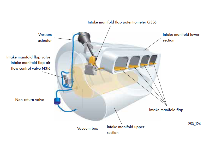
The intake cross-section (not shown) is divided into upper and lower ducts. When the flaps are activated, they rise to close off the lower duct and redirect the air into the upper duct otherwise the air flows through both ducts. An animation of the process can be see in this video. The Table below shows the state of the flaps under different conditions.
Note that the flaps are activated when the ignition is switched off and not activated when the ignition is switched on. A residual vacuum keeps the flaps activated for as long as the vacuum can be maintained. When the Ignition is switched on, the vacuum is purged and the FSI click is herd when the flaps return to the not activated position under the force from a spring.
The P1031 error means that the ECU expected the flaps to be either activated or not activated and this did not match the actual position measured by the potentiometer (G336) for at least three times consecutively. The cause could be mechanical, electrical or calibration and best diagnosed with VCDS as this is the only way to do the adaption (calibration). Measuring block 142 shows the actual and expected flap positions as well as the offset voltage and adaption status. It is also useful to display measuring block 01 to obtain the engine RPMs.
The mechanical operation of the flaps can tested by manually applying a vacuum. The vacuum pipe can be disconnected from the control valve (N316), rotated under the air intake and a vacuum created by sucking on the end of the pipe. The travel of the vacuum actuator arm should be approximately ~15mm. Placing small Tipex marks on the vacuum actuator arm can help with observing the range of movement.
The air flow control valve (N316) and vacuum can be checked as the flaps should be activated when the engine is at idle and hence the vacuum actuator arm should move by ~15mm. The control valve has two electrical connections, connection 1 (green/yellow) is 11.6v and connection 2 (purple/yellow) is 11.6v when closed and when open is 0.36v. The resistance between connection 1 and connection 2 should be approximately 30Ω.
If everything seems fine, then either the offset voltage needs to be changed or there is an issue with the potentiometer. The potentiometer has three connections, connection 1 (purple/red) is 5v ± 0.5 , connection 3 (grey/green) is ground and connection 2 (yellow/red) is ~2.6v when the flap is open and ~3.9v when the flap is closed. The resistance between connection 1 and connection 3 should be 1.80 to 2.20 kOhm. When the Basic Setting is run, the ECU will update the offset voltage and hence the voltage for the position of the flaps when they are not activated. The procedure is as follows:
Prerequisites:
[01 - Engine]
[Basic Settings - 04]
Group 142
[Go!]
Activate the Basic Setting.
[ON/OFF/Next]
Wait until Field 4 shows "ADP. O.K.".
[Done, Go Back]
[Close Controller, Go Back - 06]
Hope that helps.
A full explanation of FSI can be found in the Self-Study Programme, however for this error it is sufficient to know that the intake manifold contains flaps that are either activated or not activated. They are activated by the vacuum actuator which is controlled by the air flow control value (N316) and the position of the flaps is detected by the potentiometer (G336). This setup can be seen in the image below.
The intake cross-section (not shown) is divided into upper and lower ducts. When the flaps are activated, they rise to close off the lower duct and redirect the air into the upper duct otherwise the air flows through both ducts. An animation of the process can be see in this video. The Table below shows the state of the flaps under different conditions.
| Engine State | Flaps State |
| Ignition on | Not activated |
| Idle | Activated |
| RPM < ~3200 | Activated |
| RPM > ~3200 | Not activated |
| Ignition off | Activated |
Note that the flaps are activated when the ignition is switched off and not activated when the ignition is switched on. A residual vacuum keeps the flaps activated for as long as the vacuum can be maintained. When the Ignition is switched on, the vacuum is purged and the FSI click is herd when the flaps return to the not activated position under the force from a spring.
The P1031 error means that the ECU expected the flaps to be either activated or not activated and this did not match the actual position measured by the potentiometer (G336) for at least three times consecutively. The cause could be mechanical, electrical or calibration and best diagnosed with VCDS as this is the only way to do the adaption (calibration). Measuring block 142 shows the actual and expected flap positions as well as the offset voltage and adaption status. It is also useful to display measuring block 01 to obtain the engine RPMs.
The mechanical operation of the flaps can tested by manually applying a vacuum. The vacuum pipe can be disconnected from the control valve (N316), rotated under the air intake and a vacuum created by sucking on the end of the pipe. The travel of the vacuum actuator arm should be approximately ~15mm. Placing small Tipex marks on the vacuum actuator arm can help with observing the range of movement.
The air flow control valve (N316) and vacuum can be checked as the flaps should be activated when the engine is at idle and hence the vacuum actuator arm should move by ~15mm. The control valve has two electrical connections, connection 1 (green/yellow) is 11.6v and connection 2 (purple/yellow) is 11.6v when closed and when open is 0.36v. The resistance between connection 1 and connection 2 should be approximately 30Ω.
If everything seems fine, then either the offset voltage needs to be changed or there is an issue with the potentiometer. The potentiometer has three connections, connection 1 (purple/red) is 5v ± 0.5 , connection 3 (grey/green) is ground and connection 2 (yellow/red) is ~2.6v when the flap is open and ~3.9v when the flap is closed. The resistance between connection 1 and connection 3 should be 1.80 to 2.20 kOhm. When the Basic Setting is run, the ECU will update the offset voltage and hence the voltage for the position of the flaps when they are not activated. The procedure is as follows:
Prerequisites:
- Ignition ON
- Engine OFF
- System voltage at least 11.0 V.
[01 - Engine]
[Basic Settings - 04]
Group 142
[Go!]
Activate the Basic Setting.
[ON/OFF/Next]
Wait until Field 4 shows "ADP. O.K.".
[Done, Go Back]
[Close Controller, Go Back - 06]
Hope that helps.
Last edited:
A2Steve
A2OC Donor
Here is an attempt at a summary.
A full explanation of FSI can be found in the Self-Study Programme, however for this error it is sufficient to know that the intake manifold contains flaps that are either activated or not activated. They are activated by the vacuum actuator which is controlled by the air flow control value (N316) and the position of the flaps is detected by the potentiometer (G336). This setup can be seen in the image below.
The intake cross-section (not shown) is divided into upper and lower ducts. When the flaps are activated, they rise to close off the lower duct and redirect the air into the upper duct otherwise the air flows through both ducts. An animation of the process can be see in this video. The Table below shows the state of the flaps under different conditions.
Engine State Flaps State Ignition on Not activated Idle Activated RPM < ~3200 Activated RPM > ~3200 Not activated Ignition off Activated
Note that the flaps are activated when the ignition is switched off and not activated when the ignition is switched on. A residual vacuum keeps the flaps activated for as long as the vacuum can be maintained. When the Ignition is switched on, the vacuum is purged and the FSI click is herd when the flaps return to the not activated position under the force from a spring.
The P1031 error means that the ECU expected the flaps to be either activated or not activated and this did not match the actual position measured by the potentiometer (G336) for at least three times consecutively. The cause could be mechanical, electrical or calibration and best diagnosed with VCDS as this is the only way to do the adaption (calibration). Measuring block 142 shows the actual and expected flap positions as well as the offset voltage and adaption status. It is also useful to display measuring block 01 to obtain the engine RPMs.
The mechanical operation of the flaps can tested by manually applying a vacuum. The vacuum pipe can be disconnected from the control valve (N316), rotated under the air intake and a vacuum created by sucking on the end of the pipe. The travel of the vacuum actuator arm should be approximately ~15mm. Placing small Tipex marks on the vacuum actuator arm can help with observing the range of movement.
The air flow control valve (N316) and vacuum can be checked as the flaps should be activated when the engine is at idle and hence the vacuum actuator arm should move by ~15mm. The control valve has two electrical connections, connection 1 (green/yellow) is 11.6v and connection 2 (purple/yellow) is 11.6v when closed and when open is 0.36v. The resistance between connection 1 and connection 2 should be approximately 30Ω.
If everything seems fine, then either the offset voltage needs to be changed or there is an issue with the potentiometer. The potentiometer has three connections, connection 1 (purple/red) is 5v ± 0.5 , connection 3 (grey/green) is ground and connection 2 (yellow/red) is ~2.6v when the flap is open and ~3.9v when the flap is closed. The resistance between connection 1 and connection 3 should be 1.80 to 2.20 kOhm. When the Basic Setting is run, the ECU will update the offset voltage and hence the voltage for the position of the flaps when they are not activated.
Hope that helps.
What about adding the vcds process for calibrating the flaps? Could be useful.
I have just edited the post to add it. It is just a copy and paste from the Ross-Tech wiki.What about adding the vcds process for calibrating the flaps? Could be useful.
A2Steve
A2OC Donor
I took delivery of the FSI project today. Drives nice, underpowered compared to my TDI90 with remap but I think the performance is where it should be for an FSI.
Prior to my purchase it’s had a replacement lower inlet manifold which I know to be good (I supplied it) and a replacement high pressure fuel pump, so the hard stuff has been done.
It came to me with the P1031 fault and I thought I’d go mechanical first rather than vcds because I haven’t got a registered version yet.
I’ve just changed the N316 valve seeing as I had one here that I know had no faults. I thought I’d cracked it because after 4 re-starts and revving over 3200rpm I still haven’t got an EML showing. Unfortunately after doing a scan with my code reader I’ve still get P1031 code logged but not yet triggering the EML.
I’d considered changing the G336 while at it as well but it looks to be a pig to change (or impossible) without removing the lower inlet manifold.
I suppose the logical step next would be to carry out the calibration with vcds?
mrbroons
Well-Known Member
I took delivery of the FSI project today. Drives nice, underpowered compared to my TDI90 with remap but I think the performance is where it should be for an FSI.
Prior to my purchase it’s had a replacement lower inlet manifold which I know to be good (I supplied it) and a replacement high pressure fuel pump, so the hard stuff has been done.
It came to me with the P1031 fault and I thought I’d go mechanical first rather than vcds because I haven’t got a registered version yet.
I’ve just changed the N316 valve seeing as I had one here that I know had no faults. I thought I’d cracked it because after 4 re-starts and revving over 3200rpm I still haven’t got an EML showing. Unfortunately after doing a scan with my code reader I’ve still get P1031 code logged but not yet triggering the EML.
I’d considered changing the G336 while at it as well but it looks to be a pig to change (or impossible) without removing the lower inlet manifold.
I suppose the logical step next would be to carry out the calibration with vcds?
I presume everything is moving correctly Steve?
A2Steve
A2OC Donor
I presume everything is moving correctly Steve?
I’ll do the tippex test tomorrow once I’ve borrowed some from work ?
A2Steve
A2OC Donor
Did you clear the code and it immediately recur?
Cleared the code before running it after changing that valve. No EML yet after 4 re-starts, but I did a scan and it’s showing P1031
PlasticMac
Member
Anyone without the access to the parts you've changed already, would have spent more than the $99 VCDS Lite registration fee, and got nowhere.I’ll do the tippex test tomorrow once I’ve borrowed some from work ?
The FSI is the only modern (for the late 90s) engine fitted to the A2. The engine design included integrated electronic controllers from it's conception, rather than electronics that were bolted on to older engine designs.
Troubleshooting such an engine, and it's integrated controllers, requires the diagnostic tool (VCDS) that was developed in parallel (first released in 2000, as VAGcom).
If you've changed the manifold, then it's controller must be calibrated to that manifold assembly.
Only when it is operating as it should, will the P1031 error clear, and stay clear. And, only then will your fsi be a real FSI!
Mac.
Last edited:
I took delivery of the FSI project today. Drives nice, underpowered compared to my TDI90 with remap but I think the performance is where it should be for an FSI.
Prior to my purchase it’s had a replacement lower inlet manifold which I know to be good (I supplied it) and a replacement high pressure fuel pump, so the hard stuff has been done.
It came to me with the P1031 fault and I thought I’d go mechanical first rather than vcds because I haven’t got a registered version yet.
I’ve just changed the N316 valve seeing as I had one here that I know had no faults. I thought I’d cracked it because after 4 re-starts and revving over 3200rpm I still haven’t got an EML showing. Unfortunately after doing a scan with my code reader I’ve still get P1031 code logged but not yet triggering the EML.
I’d considered changing the G336 while at it as well but it looks to be a pig to change (or impossible) without removing the lower inlet manifold.
I suppose the logical step next would be to carry out the calibration with vcds?
Please don't just change parts and hope it fixes the problem. The post I made should contain all the information you need diagnose the issue. With only some Tipex, a pin and a multimeter you should know what is wrong in about 5 minutes. The short version of the post is as follows:
- Do the flaps have the full range of movement?
- Disconnect the pipe from the control valve
- Rotate the pipe under the air intake
- Suck it and see
- Is it being activated by the vacuum?
- Turn the ignition on to purge the vacuum
- Make a mark on the actuator arm with Tipex
- Turn the engine on (idle)
- Make another mark on the actuator arm
- Is the travel approximately ~15mm?
- Is the potentiometer functioning correctly?
- Disconnect the air intake pipe at the throttle body and move it for better access
- Remove the cover on the plug
- Backprobe connector 2 (yellow/red) with a pin/small nail and the multimeter
- Ignition on ~2.6v
- Engine on (Idle ) ~3.9v
Last edited:
A2Steve
A2OC Donor
Please don't just change parts and hope it fixes the problem. The post I made should contain all the information you need diagnose the issue. With only some Tipex, a pin and a multi-meter you should know what is wrong in about 5 minutes. The short version of the post is as follows:
Please can you (or anyone else with this error) post the answers to the questions.
- Do the flaps have the full range of movement?
- Disconnect the pipe from the control valve
- Rotate the pipe under the air intake
- Suck it an see
- Is it being activated by the vacuum?
- Turn the ignition on to purge the vacuum
- Make a mark on the actuator arm with Tipex
- Turn the engine on (idle)
- Make another mark on the actuator arm
- Is the travel approximately ~15mm?
- Is the potentiometer functioning correctly?
- Disconnect the air intake pipe at the throttle body and move it for better access
- Remove the cover on the plug
- Backprobe connector 2 (yellow/red) with a pin/small nail and the multi-meter
- Ignition on ~2.6v
- Engine on (Idle ) ~3.9v
You are completely right, there's no excuse when it can be that simple. I only changed parts simply because I had known to be good ones here and the ability to change them myself.
I'll purchase a multimeter and come back to the thread.
You can do the first two tests without the multimeter.I'll purchase a multimeter and come back to the thread.
A2Steve
A2OC Donor
You can do the first two tests without the multimeter.
Multimeter will be delivered tomorrow by amazon
")