wilco184
Member of the year 2015
Hello,
I have recently had the problem of my rear left door causing the locks to cycle when I put the key in the ignition. It was intermittent, although it happened seemingly more with a colder ambient temperature. VCDS confirmed which door was causing the issues, with the fault of 'wont de-safe' or 'can't unlock' or similar, I forget the exact words used. The locks cycling became extremely annoying, very quickly. I've seen this fault recorded on the forum before, but no documented fix for the A2.
As AJSelllors has said in another thread, problems with door microswitches on Volkswagen/Audi group cars of the same era are certainly common. I read posts mostly affecting the MKIV Golf over at TDI Club. There was an excellent post on here by Spike showing a repair video for a MKIV Golf, which I used a lot when repairing my own module. The link is here. http://www.youtube.com/watch?v=z5dtdyDDgrw
Once I knew what the common faults with these modules are, and how to remove it, I went ahead and attempted a repair.
I'll spare the details of removal, as it has been covered thoroughly by 'the grim reeper' before. I add my thanks for this, the instructions are great. I will add that I also didn't have to remove the window mechanism, the module can fit around it. The link to the instructions are here. http://www.a2oc.net/forum/showthread.php?13246-How-to-replace-rear-door-micro-switch
Once the module is removed, it looks like this. I apologise for the poor quality photographs, they were taken with my iPhone 5 under artificial light. Something I feel the iPhone lacks ability with.
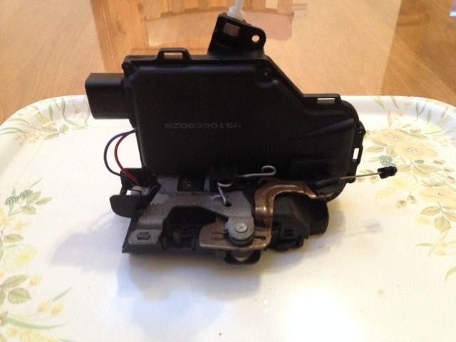
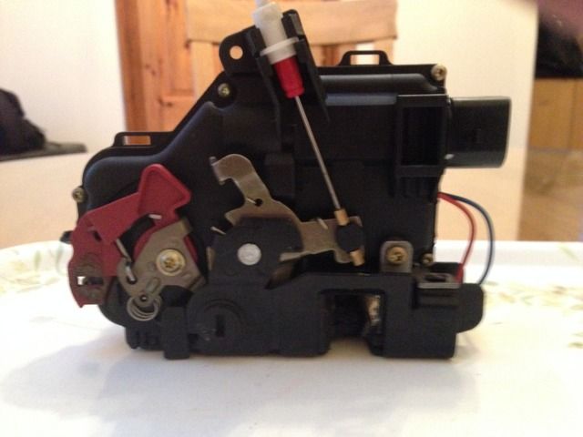
The video I've linked above shows how to disassemble the module. The A2s lock is very similar to the Golfs, and screws you need to remove are in the same places. The smaller of the two types is a T10 Torx, and the larger is T20 if I recall correctly. Once the module is split into its two halves, it looks like this.
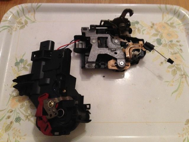
As stated in the video, the module is effectively two halves. One mechanical and one electrical. In the above picture, the electrical half is on the left hand side. With the T10 screws removed, and the red plastic piece facing down, the casing pulls apart easily. I would add not to remove the T20 screw keeping the red plastic part on, I did, and it was unnecessary and took a while to put the two springs back on. Inside, you will be able to see the main blue circuit board, two motors and various linkages.
Next, you can pull up the circuit board from the casing. It lifts fairly easily, and detaches with the two motors and connector. When removed, it looks like this.
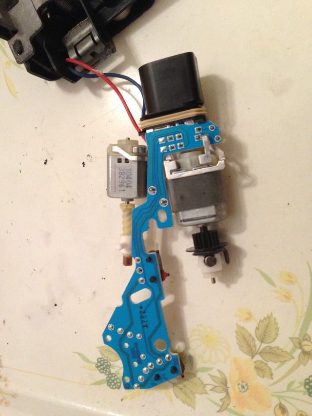
As you can see in the photograph above, my module has appeared to have kept very clean inside. There was no evidence inside the case of any ingress, and the microswitches looked as new, with the rubber seals on the plunger also looking healthy. I checked the operation of the switches with a multimeter using the resistance measurement function. A range of 200 Ohms will be fine for this. You will need to trace the tracks from the switches back to the connector pin solder terminals and measure from there. My switches operated correctly, with a measured resistance of just less than 1 Ohm. I assumed this to be normal. Under closer inspection of the terminals however, one terminal in particular looked a bit 'suspect', if you know what I mean. I can't be entirely sure, but I strongly suspect a dry and cracked solder joint was the cause, in my case. I would recommend checking this. I reflowed all of the joints on the board for good measure, and then confirmed the continuity of the switches once more.
Reassembly can then begin. It's pretty much the reverse of taking it apart. Make sure not to over tighten the screws as the soft plastic threads can easily strip. The module can then be installed back in the car. Remember to replace the thin foam cover over the module; I forgot to and left it inside the door, I'm still annoyed about forgetting this. Plug the module in and test. I wouldn't replace the aluminium inner card without testing as I put a linkage back incorrectly first time and the door wouldn't lock, although I'm sure this would be difficult to replicate how I misplaced the linkage.
Reassemble the rest of the door and your done!")
It's good not the have the annoying lock cycle and convenience module fault anymore. In fact, with my Q to AF CCCU conversion done recently too, I'm very happy not to have any CCCU related faults stored. Good times.
I hope this is of some use. If you're confident with stripping the door down, I'd say it's certainly worth trying. Especially seeing as the module costs a considerable amount.
Regards,
Matt.
I have recently had the problem of my rear left door causing the locks to cycle when I put the key in the ignition. It was intermittent, although it happened seemingly more with a colder ambient temperature. VCDS confirmed which door was causing the issues, with the fault of 'wont de-safe' or 'can't unlock' or similar, I forget the exact words used. The locks cycling became extremely annoying, very quickly. I've seen this fault recorded on the forum before, but no documented fix for the A2.
As AJSelllors has said in another thread, problems with door microswitches on Volkswagen/Audi group cars of the same era are certainly common. I read posts mostly affecting the MKIV Golf over at TDI Club. There was an excellent post on here by Spike showing a repair video for a MKIV Golf, which I used a lot when repairing my own module. The link is here. http://www.youtube.com/watch?v=z5dtdyDDgrw
Once I knew what the common faults with these modules are, and how to remove it, I went ahead and attempted a repair.
I'll spare the details of removal, as it has been covered thoroughly by 'the grim reeper' before. I add my thanks for this, the instructions are great. I will add that I also didn't have to remove the window mechanism, the module can fit around it. The link to the instructions are here. http://www.a2oc.net/forum/showthread.php?13246-How-to-replace-rear-door-micro-switch
Once the module is removed, it looks like this. I apologise for the poor quality photographs, they were taken with my iPhone 5 under artificial light. Something I feel the iPhone lacks ability with.


The video I've linked above shows how to disassemble the module. The A2s lock is very similar to the Golfs, and screws you need to remove are in the same places. The smaller of the two types is a T10 Torx, and the larger is T20 if I recall correctly. Once the module is split into its two halves, it looks like this.

As stated in the video, the module is effectively two halves. One mechanical and one electrical. In the above picture, the electrical half is on the left hand side. With the T10 screws removed, and the red plastic piece facing down, the casing pulls apart easily. I would add not to remove the T20 screw keeping the red plastic part on, I did, and it was unnecessary and took a while to put the two springs back on. Inside, you will be able to see the main blue circuit board, two motors and various linkages.
Next, you can pull up the circuit board from the casing. It lifts fairly easily, and detaches with the two motors and connector. When removed, it looks like this.

As you can see in the photograph above, my module has appeared to have kept very clean inside. There was no evidence inside the case of any ingress, and the microswitches looked as new, with the rubber seals on the plunger also looking healthy. I checked the operation of the switches with a multimeter using the resistance measurement function. A range of 200 Ohms will be fine for this. You will need to trace the tracks from the switches back to the connector pin solder terminals and measure from there. My switches operated correctly, with a measured resistance of just less than 1 Ohm. I assumed this to be normal. Under closer inspection of the terminals however, one terminal in particular looked a bit 'suspect', if you know what I mean. I can't be entirely sure, but I strongly suspect a dry and cracked solder joint was the cause, in my case. I would recommend checking this. I reflowed all of the joints on the board for good measure, and then confirmed the continuity of the switches once more.
Reassembly can then begin. It's pretty much the reverse of taking it apart. Make sure not to over tighten the screws as the soft plastic threads can easily strip. The module can then be installed back in the car. Remember to replace the thin foam cover over the module; I forgot to and left it inside the door, I'm still annoyed about forgetting this. Plug the module in and test. I wouldn't replace the aluminium inner card without testing as I put a linkage back incorrectly first time and the door wouldn't lock, although I'm sure this would be difficult to replicate how I misplaced the linkage.
Reassemble the rest of the door and your done!
It's good not the have the annoying lock cycle and convenience module fault anymore. In fact, with my Q to AF CCCU conversion done recently too, I'm very happy not to have any CCCU related faults stored. Good times.
I hope this is of some use. If you're confident with stripping the door down, I'd say it's certainly worth trying. Especially seeing as the module costs a considerable amount.
Regards,
Matt.
Last edited:
